E-mail: info@plymachine.com WhatsApp:+8619553901259

Views: 0 Author: Site Editor Publish Time: 2026-09-05 Origin: Site

Mill throughput rarely hits a wall because of the peeling lathe itself. The most common bottleneck in plywood manufacturing is inconsistent, inefficient log feeding. Manual or poorly configured log handling leads to lathe starvation, inaccurate block centering, high labor overhead, and significant raw material waste. Upgrading to an automated wood log conveyor and synchronized log loader system resolves these bottlenecks. This guide breaks down how to evaluate layout configurations, technical specifications, and integration strategies to maximize wood recovery and operational uptime—from initial log loading to finished veneer sheets—in automatic veneer peeling lines.
Throughput Dependency: A high-speed veneer peeling line requires a continuous, synchronized feed; intelligent wood log conveyors eliminate lathe idle time and completely replace manual handling risks.
Precision Centering Equals Yield: Integrating advanced log loaders with X-Y scanning and centering mechanisms directly increases veneer recovery rates by minimizing rounding waste.
Adaptability to Peeling Technology: Modern layouts must seamlessly feed spindle, spindleless, or hybrid peeling solutions to maximize wood recovery across varying log diameters.
Layout Dictates Efficiency: Selecting between linear, L-shaped, or U-shaped conveyor layouts depends heavily on facility footprint, debarker positioning, and buffer zone requirements.
Defining a successful log handling upgrade requires establishing strict performance baselines on the mill floor. A properly integrated system must achieve at least 95% lathe utilization during active shifts. Feed-related downtime, often caused by jammed blocks or misaligned logs, should decrease by a minimum of 40%. Complete elimination of manual sorting is another primary success criterion. Meeting these targets ensures mechanical upgrades translate directly into measurable production volume increases. Operators shift from physically manipulating heavy timber with peaveys to monitoring automated sequences via control panels.
The operational limitations of forklift-dependent or manual log manipulation become obvious at high production speeds. Forklifts introduce unpredictable cycle times and create dangerous traffic zones on the mill floor. A forklift operator trying to feed a high-speed lathe constantly fights against the clock, often dropping blocks or misaligning them on the deck. Operators struggle to maintain the rapid, relentless pace required by modern machinery. Continuous-flow, intelligent wood conveyor lines solve this logistical nightmare. They automatically sort, space, and convey blocks without human intervention. The conveyor system paces the logs perfectly to match the exact cycle time of the downstream machinery.
Consistent feed rates and automated sorting directly impact overall wood recovery. Manual handling often results in dropped blocks, shattered ends, or deep gouges from forklift tines. Automated systems cradle and transport the timber smoothly, preventing mechanical damage before peeling. Proper staging prepares blocks for optimal engagement with the lathe charger. Overall veneer quality improves significantly when logs enter the cutting zone in pristine condition, allowing for continuous, unbroken veneer ribbons. You eliminate the split ends and fractured cores that typically result from rough manual handling.
Tracking specific production metrics reveals the true value of automation. You should monitor the block count processed per minute and the exact time it takes from dropping a spent core to engaging a new block. Automated systems reduce this transition time to mere seconds. The lathe spends more time cutting wood and less time waiting for the next log. This continuous utilization is the only way to achieve maximum output from your peeling equipment.
Evaluating heavy-duty wood log conveyors requires analyzing the specific physical properties of your timber supply. You need to match the conveying medium to the log weight, moisture content, and bark conditions. Using the wrong conveyor type leads to constant slippage, jammed chains, and premature equipment failure.
Conveyor Type | Best Application | Key Advantages | Operational Limitations |
|---|---|---|---|
Heavy-Duty Drag Chain | Large, wet, unbarked logs | Extreme durability, handles high impact loading | Requires high torque, higher maintenance on chain links |
Spiked Roller Bed | Frozen or heavily sapped timber | Aggressive traction, prevents slippage | Can cause minor surface damage to softwoods |
Heavy-Duty Belt | Pre-debarked, lighter blocks | Smooth transport, protects wood surface | Prone to tearing if sharp debris is present |
Drive system requirements demand the integration of Variable Frequency Drives (VFDs). VFDs allow precise speed matching across the entire production line. They communicate directly with the lathe PLC via Ethernet/IP or Profinet protocols. The conveyor must sync perfectly with debarkers and lathes to prevent pile-ups or empty pockets. Intelligent sorting capabilities rely on automated log transporters equipped with pneumatic or hydraulic kickers. These systems route blocks into different bins based on diameter, species, or structural quality. Sorting happens long before blocks reach the peeling stage, allowing the lathe to run batches of uniform timber.
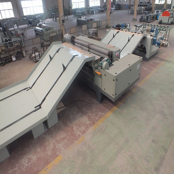
Precision log loaders utilize specific mechanical actions to manage the flow of timber. Step feeders lift and separate logs from a bulk pile, moving them upward in a staggered sequence. Hydraulic kicker arms eject logs laterally onto adjacent transfer decks with high velocity. Singulating unscramblers rotate and agitate the pile until logs fall into a single-file line. A well-engineered log loader isolates single blocks from the bulk surge. It stages them perfectly for the lathe charger, preventing double-feeding and catastrophic jams.
Ensuring seamless handoffs between the debarking station, the buffer deck, and the peeling lathe is mandatory. The transition points are where most mechanical faults occur. Feed mechanisms and charger designs must adapt to the specific lathe type installed in the mill. They must accommodate traditional spindle lathes, modern spindleless systems, and advanced hybrid peeling solutions. This adaptability ensures maximum wood recovery across all log profiles. The charger must grip the block securely and transfer it into the cutting zone without losing the calculated center axis.
Linear layouts work best for high-speed, continuous flow operations where facility length permits. A straight line minimizes log direction changes, drastically reducing the risk of jams and mechanical wear. Logs move from the debarker straight through to the lathe without requiring complex transfer decks. You avoid the need for cross-transfer chains and right-angle kickers. However, linear layouts demand significant floor space, often requiring building extensions in older facilities.
U-Shape or L-Shape layouts become necessary for compact footprints or retrofitting older mills. These folded layouts require specialized transfer decks. Hydraulic kickers and cross-transfer chains must change log orientation 90 or 180 degrees without causing bottlenecks. Designing these transition points requires precise engineering to ensure logs do not skew or bind when changing direction. The transfer chains must run at slightly different speeds to pull the log straight as it moves around the corner.
Sizing the surge deck between the debarker and the log loader requires precise calculation. This buffer zone prevents lathe starvation during upstream delays, such as a jammed debarker or a dull knife change. You must calculate optimal buffer capacity based on average log diameter and lathe cycle time. Optimizing log deck units for medium-sized logs around 0.45m requires different spacing than small-diameter plantation timber.
Measure the average cycle time of the peeling lathe from block engagement to core drop.
Determine the maximum processing speed of the upstream debarker under optimal conditions.
Calculate the time differential between debarking a single log and peeling a single block.
Multiply this time differential by the target continuous run time to find the required block count for the surge deck.
Convert the block count into linear meters based on your average log diameter to determine the physical length of the accumulation deck.
Positioning 3D scanners and optical sensors within the log loader layout is critical for block centering. The layout geometry directly affects the accuracy of geometric centering before the block engages the peeling knife. Scanners must be mounted in a vibration-free zone, typically just before the pendulum charger. The system scans the block's topography to calculate the optimal yield center rather than just the geometric center. Accurate scanning reduces rounding waste. It ensures the lathe produces full-sheet veneer much faster, maximizing the usable volume of every single log.
Evaluating the durability of photoelectric sensors, limit switches, and encoders is a strict engineering requirement. These electronic components operate in harsh, high-vibration, high-debris environments. They must carry high IP ratings (IP67 or IP69K) to withstand dust, sap, and high-pressure washdowns. Centralized PLC control systems provide real-time monitoring of every motor and sensor on the line. They offer rapid fault diagnostics, pinpointing exactly which switch failed. Integration with mill-wide ERPs allows plant managers to conduct real-time yield tracking and production forecasting.
Assessing frame steel thickness and structural design prevents premature equipment failure. Look for wear-resistant liners, such as Hardox 450 or 500, in high-impact zones where logs drop or scrape. Heavy-duty bearing housings are non-negotiable for rollers handling massive dynamic loads. Evaluate the lifespan of conveyor chains under continuous shock loading conditions. Check hydraulic cylinder seals for their ability to withstand rapid cycling and high system pressures. Robust material specifications reduce maintenance frequency and extend the operational life of the entire handling system.
Hydraulic systems require careful evaluation. Proportional valves offer significant advantages over standard directional valves for kicker arms. Proportional valves allow for smoother acceleration and deceleration of heavy logs. This controlled movement reduces structural fatigue on the conveyor frame and prevents logs from being thrown too violently across the deck. High-resolution encoders for the X-Y scanners provide more data points for the PLC. This allows the system to calculate the true yield center accurately, especially on logs with severe sweep or pistol grip.
Balancing the need for high-torque startup capabilities with overall energy efficiency reduces utility overhead. Oversized motors waste electricity during idle periods. Undersized motors burn out quickly when attempting to move a fully loaded deck from a dead stop. Regenerative braking systems on VFDs capture lost energy during deceleration phases. Efficient hydraulic power units utilize variable displacement pumps. These pumps only generate flow when required, reducing heat generation and lowering operational costs significantly over the equipment's lifespan.
Highly tapered, swept, or oversized logs frequently cause jams in poorly designed systems. Undersized logs can slip through gaps in the transfer decks, causing severe mechanical binding. Mitigate this risk by specifying log loaders with adjustable stroke lengths and dynamic hydraulic pressures. Ensure conveyors have adequate clearance and robust singulation capabilities to handle irregular shapes smoothly. The mechanical design must account for the worst-case log profile expected from your timber supply, not just the perfectly cylindrical ideal.
Prolonged production halts during equipment replacement destroy quarterly output targets. Minimizing installation downtime in existing mills requires aggressive project management. You must plan the installation down to the hour to avoid extending scheduled outages.
Conduct a full 3D laser scan of the existing mill floor to identify structural columns, underground trenches, and overhead crane clearances.
Assemble and test all modular conveyor sections at the manufacturer's facility to verify PLC logic and hydraulic integrity.
Demolish the existing manual log deck during a scheduled holiday shutdown, capping old hydraulic lines and pulling new electrical runs.
Install the new structural frames, leveling them precisely using laser transits to ensure perfect alignment with the lathe charger.
Execute a dry run of the automated sequence using dummy logs to calibrate sensor timing and kicker arm pressure before introducing live timber.
Poor post-installation support cripples a mill when proprietary components fail. Difficulty sourcing replacement parts from international manufacturers leads to extended downtime. Vet vendors based on domestic parts availability and the strength of their local distribution networks. Demand comprehensive warranties that cover both parts and labor for the critical first year of operation. Ensure the manufacturer has localized technical support networks ready to deploy field engineers within 24 hours of a catastrophic failure.
Accidents or system damage often occur due to operator unfamiliarity with automated sequences. Moving from manual control to HMI-driven automation requires a shift in operator mindset. Implement comprehensive lockout/tagout (LOTO) protocols specifically designed for complex hydraulic and electrical systems. Install physical guarding, safety fences, and light curtains around all moving parts. Mandate vendor-led training on HMI interfaces, fault recovery procedures, and routine maintenance tasks before the final project handover.
To successfully upgrade your log handling infrastructure and maximize the yield of your veneer peeling line, execute the following actions:
Conduct a detailed time-study of current lathe idle times to identify exact feeding bottlenecks and baseline your current production metrics.
Map the existing facility footprint using 3D scanning to determine available space for buffer decks and transfer conveyors.
Request specific layout proposals and hard throughput guarantees from shortlisted equipment manufacturers based on your exact log diameter averages.
Audit your current electrical and hydraulic infrastructure to ensure it can support the variable frequency drives and high-pressure power units required for automation.
A: Conveyor speeds must be variable, typically controlled via VFD. This allows the system to match the exact cycle time of the peeling lathe, debarker, and downstream clipping processes. Variable speed ensures a continuous supply of timber without overwhelming the buffer deck or causing log pile-ups.
A: It singulates logs and stages them precisely for the charger. This eliminates manual handling delays and unpredictable forklift cycle times. It ensures the lathe is immediately fed with a perfectly aligned block as soon as the previous core is dropped, maximizing active cutting time.
A: Yes, provided the system is equipped with optical sensors and dynamic hydraulic kickers. These components adjust automatically to varying diameters, ranging from small plantation timber to large old-growth logs. Proper sensor integration prevents jams and ensures smooth transitions regardless of log taper.
A: For hybrid lines combining spindle and spindleless peeling, the log loader and charger must be precisely calibrated. They center the block for the initial spindle peel and ensure a smooth, aligned transition when the block is dropped to the spindleless mechanism, maximizing core recovery.
A: Footprints vary widely based on capacity and log length. A standard automated line with debarking, buffer decks, log loading, and peeling typically requires a minimum length of 30 to 50 meters. Compact mills often utilize folded L-shape or U-shape layouts to fit within tighter constraints.
A: Advanced log loaders work in tandem with X-Y scanners and pendulum chargers. The scanners map the log's topography to calculate the optimal yield center. The charger then grips the block based on these coordinates, ensuring it is geometrically aligned before engaging the lathe spindles.
A: Routine maintenance includes lubricating heavy-duty bearings and drag chains. Technicians must inspect hydraulic hoses for wear and clear bark debris from optical sensor pathways. Regularly checking the tension of drive chains or belts prevents slippage and ensures consistent power transmission.